The short version
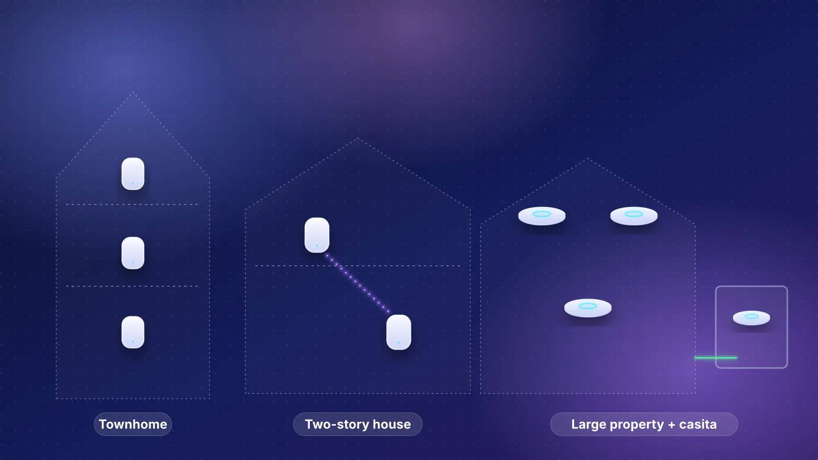
- The outside shell is the expensive part. In NIST's laboratory tests, an 8-inch hollow concrete block wall cost about 15 dB at 5 to 5.5 GHz and about 16 dB at 6 to 6.5 GHz, while a drywall panel cost under 1 dB. Keep routers and access points toward the middle of the house, not on the exterior walls of the rooms they serve.
- Stucco on framing hides a metal mesh. The International Residential Code calls for metal or wire lath under stucco on wood framing, but not over block. eero says walls with "lath, or chicken wire" are "particularly hard for wifi signals". We found no published measurement of a stucco-over-lath wall at Wi-Fi frequencies, so treat those walls as unknown and measure.
- One unit per floor, and wire the floor crossing if you can. The ITU's planning value for a house floor is 5 dB at 2.4 GHz and 7 dB at 5.2 GHz; in the concrete-floor case the ITU cites, air ducts under the floor raised the loss from 20 to 36 dB.
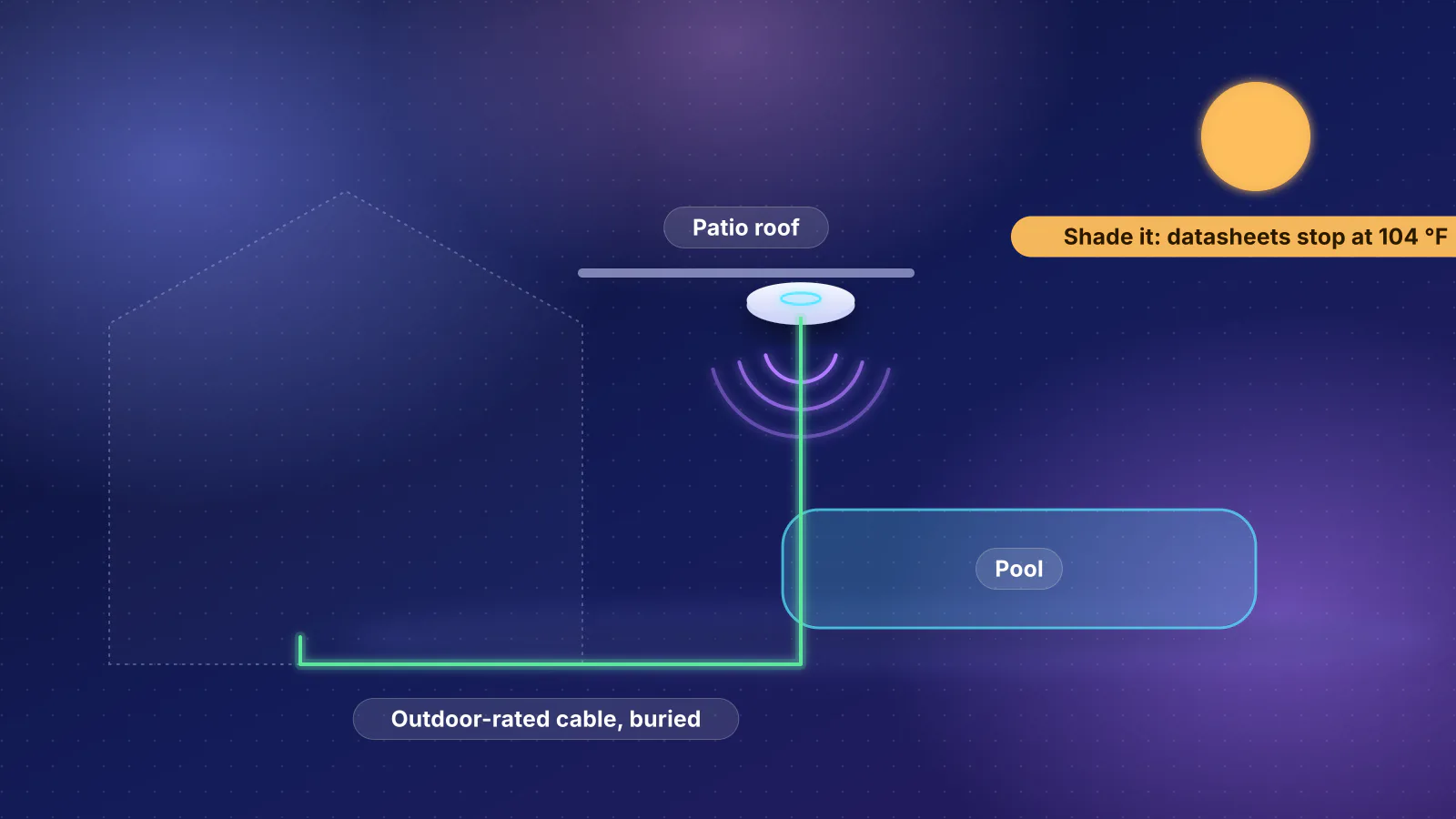
- The patio needs its own plan. In measurements the ITU has collected, coated (low-E) glass ranged from no obvious penalty (a house-like US building with low-E windows: 8.5 dB mean entry loss at 5 GHz) to about 20 dB more loss than plain glass (silver-coated glazing in a French lab building at 3.6 GHz). If you use the patio or pool area daily, an outdoor unit on a cable beats a stronger indoor one.
- Ceiling access points go on the ceiling. They're characterized for overhead mounting; on a wall, use the maker's arm mount or a wall model. Mesh units go in the open at the height their maker gives, which differs: eero says halfway up the wall, TP-Link says 1 to 1.5 ft off the floor.
- Plan with a zone list, then check it with your phone. The worksheet below lists each room, the unit that serves it and what lies between; the two worked layouts show it filled in.
This article is about where units go in a house with dense walls. For how many units to buy, see how many mesh nodes you need; for why a badly placed node stays slow, why mesh Wi-Fi doesn't fix slow rooms, which also has each mesh maker's spacing rules.
What walls, floors and windows cost, measured
Loss is counted in decibels: every 3 dB halves the signal power, and 10 dB leaves a tenth. The table below gives only figures someone measured or a standards body published, each with the frequency it applies to. Two cautions before using it:
- NIST skipped 2.4 GHz. Its 1997 study (NIST IR 6055) measured 0.5 to 2 GHz and 3 to 8 GHz. The 5 GHz band and the 6 GHz band (5.925 to 7.125 GHz, per Cisco) fall in the upper range; 2.4 GHz falls in the gap, so read NIST's 2 and 3 GHz values as a bracket for it, not a measurement. The ITU's material model, which covers 1 to 100 GHz, has solid concrete absorbing about twice as many decibels per inch at 6.5 GHz as at 2.4 GHz (RouterHaus arithmetic from ITU-R P.2040-4, Table 3 and equation 27a).
- A lab panel isn't a wall in a house. NIST measured bare specimens between two antennas with reflections blocked. In three houses in Blacksburg, Virginia, at 5.85 GHz, Durgin, Rappaport and Xu fitted 3.6 to 5.6 dB per interior plaster or plasterboard wall, far more than NIST's drywall panel. A real wall has two layers of board, studs and wiring, and a fitted value folds in everything else along the path.
| Material or barrier | Loss | Frequency | Source and setup |
|---|---|---|---|
| Drywall panel, 6 to 16 mm | 1 dB or less | 0.5–2 and 3–8 GHz | NIST IR 6055, laboratory specimen |
| Interior plaster or plasterboard walls in a house | 3.6 to 5.6 dB per wall (4.7 dB typical) | 5.85 GHz | Durgin et al. 1998, fitted from measurements in three Virginia homes |
| Clear glass, 6 to 19 mm | 1.4 to 3.9 dB at 2 GHz; about 1 dB or less at 5–6.5 GHz | 2 and 5–6.5 GHz | NIST IR 6055, laboratory specimen |
| Hollow concrete block wall, 203 mm (8 in), unfilled | 8 to 11.5 dB (11 dB at 2 GHz); 15 dB at 3 GHz; about 15 dB at 5–5.5 GHz; 16 dB at 6–6.5 GHz; 17 dB at 7 GHz | 0.5–2 and 3–7 GHz | NIST IR 6055, laboratory wall, single row of block |
| Brick exterior wall of a house | 10.2 dB | 5.85 GHz | Durgin et al. 1998, one home, fitted value |
| Plain concrete, 102 mm (4 in) | 13 to 18 dB at 2 GHz; 17 to 29 dB at 5–6.5 GHz | 2 and 5–6.5 GHz | NIST IR 6055, eight concrete mixes |
| Plain concrete, 203 mm (8 in) | 29 to 35 dB at 2 GHz; about 45 to 65 dB at 5–6.5 GHz | 2 and 5–6.5 GHz | NIST IR 6055, laboratory slabs |
| Steel bar grid, 19 mm bars, 70 mm spacing | 10 to 16 dB at 0.5–2 GHz; about 2 to 3 dB at 5–7 GHz | 0.5–2 and 5–7 GHz | NIST IR 6055 (the 140 mm grid: under 4 dB, and under 1 dB at 5–7 GHz) |
| Floor of a house (planning value) | 5 dB at 2.4 GHz; 7 dB at 5.2 GHz | 2.4 and 5.2 GHz | ITU-R P.1238-13, Table 5 |
| Reinforced concrete floor with suspended ceiling | 20 dB; 30 dB with light fixtures; 36 dB with air ducts under the floor | 5.2 GHz | ITU-R P.1238-13, measured case it cites |
| Rooms behind silver-coated double glazing vs plain double glazing (same building) | 27 dB average vs about 7 dB behind the plain windows | 3.6–3.7 GHz (the report's "3 GHz") | ITU-R Report P.2346-6, §20 (Orange Labs building, Belfort, France) |
| Foil-backed plasterboard plus metallized double glazing added to a small house | 5 to 10 dB more than the uninsulated house; foil over every window and door added about 5 dB more | 88 MHz to 5.76 GHz (includes 2.41 and 5.76 GHz) | ITU-R Report P.2346-6, §6 (UK house) |
| Foil-backed insulation in exterior walls | "as much as 4 dB" added | 5.85 GHz | Durgin et al. 1998 |
| Stucco over metal or wire lath | No published measurement found | None | See the next section |
Three things the table says about a block or stucco house. The block or concrete shell costs ten times or more the signal of an interior wall panel (10 dB is a factor of ten). Loss through dense material climbs from 2 GHz to 5 and 6 GHz, so the bands that carry the most speed suffer most; NIST also found that, in materials that don't conduct electricity, loss per unit thickness rises with density, so a block wall with grout-filled cores should cost more than the hollow wall it tested (our inference; NIST didn't test grouted block). And 6 GHz loses only about 1 dB more than 5 GHz through NIST's block, about the same as the extra free-space loss between the bands: 1.5 dB from 5.5 to 6.5 GHz (RouterHaus arithmetic), and Cisco puts the total drop from the bottom of the 5 GHz band to the top of the 6 GHz band at "less than 3 dB". Where 6 GHz falls short in a home is transmit power (see what blocks Wi-Fi).
Stucco on block, or stucco on lath
"Stucco" describes the finish, not the wall behind it, and the two common constructions behave differently:
- Stucco on concrete block. The 2021 International Residential Code's lath section carries an exception: "Lath is not required over masonry, cast-in-place concrete, precast concrete or stone substrates" prepared to the standard it references (Section R703.7.1). Here the block dominates: use NIST's block row as a starting point and expect more if the cores are grouted.
- Stucco on wood framing. The same section says "Expanded metal, welded wire, or woven wire lath shall be attached to wood framing members or furring." That puts a continuous metal mesh across the whole wall.
Our guide to running Ethernet explains how to tell which you have: the wall's thickness at a window opening, or the sound when you knock on it. Some houses mix the two from floor to floor, so check each floor.
What we know about lath. eero's placement guide says "Older houses with dense materials like plaster, lath, or chicken wire in the walls are particularly hard for wifi signals." That's a maker's qualitative statement, not a figure. We found no laboratory or field measurement of a stucco-over-lath wall at 2.4, 5 or 6 GHz. Three measured results point in the same direction:
- The finer a metal grid, the more it blocks. NIST's two steel bar grids differed only in spacing. At 0.5 to 2 GHz, where the wavelength (15 cm and up) is longer than both grids' openings, the 70 mm grid cost 10 to 16 dB and the 140 mm grid under 4 dB. At 5 to 7 GHz, with wavelengths near the 70 mm grid's opening, the same grid cost only about 2 to 3 dB.
- Fine metal mesh in a house attenuated at 5.85 GHz. Durgin's team reported that window screens "appeared to attenuate propagation", and that rooms with sliding glass doors, which a screen never more than half covers, "showed consistent decreases in path loss".
- Thin metal layers add measurable loss. Foil-backed insulation added up to 4 dB in Durgin's homes; foil-backed plasterboard with metallized glazing added 5 to 10 dB in the UK house in the ITU report.
Wavelength is the speed of light divided by frequency: about 12 cm (5 in) at 2.4 GHz, 5.5 cm (2 in) at 5.5 GHz and 4.6 cm (1.8 in) at 6.5 GHz (RouterHaus arithmetic). If you can see the lath, at an unfinished garage wall or an attic gable, compare its openings with those lengths: openings much smaller than the wavelength put it in the range where NIST's denser grid blocked most of the signal. NIST didn't test a mesh that fine, so that's a direction, not a number. The practical rule: don't plan on Wi-Fi passing through a stucco-on-frame exterior wall, and measure before you rely on it.
Floors and the ducts inside them
An upper floor in a house is usually wood framing, and the ITU's planning value for it is 5 dB at 2.4 GHz and 7 dB at 5.2 GHz. That's the reason for the RouterHaus rule of one unit per floor, and for wiring the link between floors first; the reasoning is in walls and floors: the numbers. Concrete floors are a different order: NIST's 4-inch slabs cost 17 to 29 dB at 5 to 6.5 GHz. A slab-on-grade ground floor doesn't matter for Wi-Fi, but a concrete floor between levels does: wire across it.
Ducts can matter as much as the floor itself. In measurements the ITU cites at 5.2 GHz, a reinforced concrete floor with a suspended ceiling cost 20 dB on average, and 36 dB with air ducts under the floor. That case was concrete, but metal ductwork is in many wood floors too. Supply registers in the downstairs ceiling tell you ducts run through the floor cavity above them. Keep a ceiling access point, and the straight-line path between two mesh units on different floors, away from the main trunk.
Low-E glass and the patio
For a patio or pool, the signal has to leave through the shell: a block or stucco wall, or glass. Plain glass is cheap to cross (about 1 dB at 5 to 6.5 GHz in NIST's tests). Coated glass is the variable:
- In Orange's lab building in Belfort, France, measured at 3.6 to 3.7 GHz (the report's "3 GHz" band), a flat with silver-coated double glazing averaged 27 dB of loss from outside, against about 7 dB just behind plain double glazing in a break room of the same building (ITU-R Report P.2346-6, §20).
- In US measurements at 5 GHz, the mean building entry loss was 8.5 dB for a house-like building with "standard double pane low-emissivity windows" and 29 dB for a "green" office building with low-E glass plus a reflective thermal coating (§13). So "low-E" alone doesn't tell you the loss; the coating does.
- The ITU's building entry loss model splits buildings into "traditional" and "thermally efficient" (metallized glass, foil-backed panels). Its median for a horizontal path is about 15 dB for traditional buildings and 31 dB for thermally efficient ones at 2.4 GHz, with a similar gap at 5.5 and 6.5 GHz (RouterHaus arithmetic from ITU-R P.2109-2, Table 1). The ITU's report cautions that for two modern houses this model gave losses "much higher than measurements at lower frequencies", possibly because of "the different types of low-E glazing".
Those are outdoor-to-indoor measurements, and the ITU report notes about its US data that entry losses "may not necessarily be equated to building exit losses", so treat them as a guide to the size of the problem, not a figure for your patio. The reliable patio fix is a unit outside the shell: an outdoor mesh unit such as the eero Outdoor 7 or Deco BE65-Outdoor, or an outdoor access point, fed by a cable through the wall. eero says the Outdoor 7 needs "a PoE+ (802.3at) connection or better"; the catalog records the Deco BE65-Outdoor as taking 802.3at PoE or AC power. Pick one from the same family as your indoor units. Without a cable, put the indoor unit nearest the patio on an inside wall that faces an uncoated door or window, and measure.
Height and mounting: what the makers say
Mesh units and ceiling access points have different antenna patterns, so they want different spots.
| Maker and product type | What the maker says |
|---|---|
| eero (tabletop mesh) | "eeros radiate their signal more upwards than downwards, but mostly along the plane they're placed on. It's best to place your eeros at a height halfway between the floor and the ceiling, not on the ground." Keep them out of cabinets and away from heat sources and direct sunlight. |
| TP-Link Deco (tabletop mesh) | "Place your satellite Deco at the same height as the source Deco. 1-1.5 ft off the floor is ideal." Keep units "away from walls and metal objects"; "Metal, walls, and floors can all interfere with wireless signals". |
| NETGEAR (mesh satellites, general guidance) | "higher satellite placement can offer a clearer signal path and also reach devices upstairs"; aim for "a direct line of sight to other nodes". |
| Ubiquiti UniFi (ceiling access points) | Presents its access points' radiation plots for overhead mounting: 0° elevation is "straight under the AP", and the azimuth marks are directions around the AP "when mounted overhead". For a ceiling-style AP on a wall, Ubiquiti sells arm mounts that provide "similar coverage to a ceiling mount". The U7 Pro lists "Ceiling, Wall" mounting; the U7 Pro Wall is made for walls. |
| eero PoE 7 | Placement "Ceiling/wall mounted"; "Professional installation recommended." |
| TP-Link Omada | Sells separate ceiling-mount (EAP723) and wall-plate (EAP725-Wall) models. We found no TP-Link guidance on mounting height for them. |
What this means in a stucco or block house:
- Mesh units: on a shelf or table in the open, toward the center of the floor, away from the exterior walls and any large metal object. eero and TP-Link disagree on height; follow your own maker, and keep units in one system at similar heights.
- Ceiling access points: centered on the area they serve, on the ceiling of that floor. A downstairs ceiling AP serves downstairs; plan one per floor rather than counting on it through the floor above. If you must use a wall, use a wall model or the maker's arm mount rather than screwing a ceiling AP flat to the wall.
- Heat: Ubiquiti's datasheet gives the U7 Pro an ambient operating range of −22 to 104 °F. Mount it in the room, with only the cable in the attic. Our Phoenix provider guide covers heat and the provider's own box.
The placement worksheet
Do this on a sketch of each floor before you buy or mount anything:
- List the zones that matter, floor by floor, including outdoor areas you use: office, family room, bedrooms, patio, pool, a detached casita.
- Mark the fixed points: where the internet comes in, any existing Ethernet or coax, the stairs, the exterior wall type on each floor, coated glass doors, and ceiling registers that show where ducts run.
- Pencil in the units, starting from the number the coverage rule gives, then assign each zone to the unit that should serve it.
- For each zone, count what lies on the straight line to its unit: interior walls, exterior walls (and which kind), floors, glass. Do the same for each link between mesh units.
- Flag any zone or link that crosses an exterior wall, a floor with ducts, or coated glass. Those are the places to move a unit, run a cable or add a unit.
- After installing, add a column with what your phone measures in each zone (see below).
The next section fills it in for one house, two ways.
Two layouts for a 3,000 sq ft two-story stucco house
The example house
An assumed house, not a measured one; replace each detail with yours. 3,000 sq ft: about 1,700 downstairs (office and living room at the front, kitchen and family room at the back, a guest bedroom in a back corner) and 1,300 upstairs (a loft at the top of central stairs, the primary bedroom at the front, two bedrooms at the back). Stucco outside, over block downstairs and over framing with wire lath upstairs. Drywall interior walls. A wood-framed upper floor with the downstairs ducts running through it. The internet arrives at the garage wall at the front. A covered patio and pool across the back, reached through a low-E sliding door. No Ethernet yet; an attic above the upstairs.
How many units. By the RouterHaus rule with block or stucco walls, 3,000 ÷ 1,000 = 3 access points, at least one per floor, and the planner gives three for this house. With drywall inside, the interior alone works out to 3,000 ÷ 1,800 = 1.67, so two, and the masonry shell is the reason for a third: the far rooms and the patio, which no indoor unit reaches through the shell for certain. Both layouts below start from that.
Layout A: three mesh units
- Main unit: in the living room on an interior wall, toward the center of the downstairs, connected by one cable to the provider's equipment at the garage wall. At the garage wall it would sit at one end of the house, with most rooms several walls away.
- Upstairs satellite: in the loft at the top of the stairs, roughly above the main unit, so its link crosses one floor through the open stairwell rather than through a duct run. This is the first link to wire; stacked closets or a chase are the usual route.
- Third unit: either indoors on an interior wall of the family room, which covers the back rooms and reaches toward the patio through the slider, or an outdoor unit under the patio cover on a cable, which covers the patio and pool directly. Pick the outdoor unit if the patio is used daily.
Any three-unit kit from one maker fits this layout; the two-story plan in our home-type guide shows what the planner picks for a similar house and what changes once the satellites are wired.
Layout B: two ceiling access points
- Downstairs: one ceiling access point in the hall between the living room and the family room, near the center of the floor and off the duct trunk.
- Upstairs: one in the hall ceiling near the loft, fed from the attic, the easiest route in this house (see attic drops).
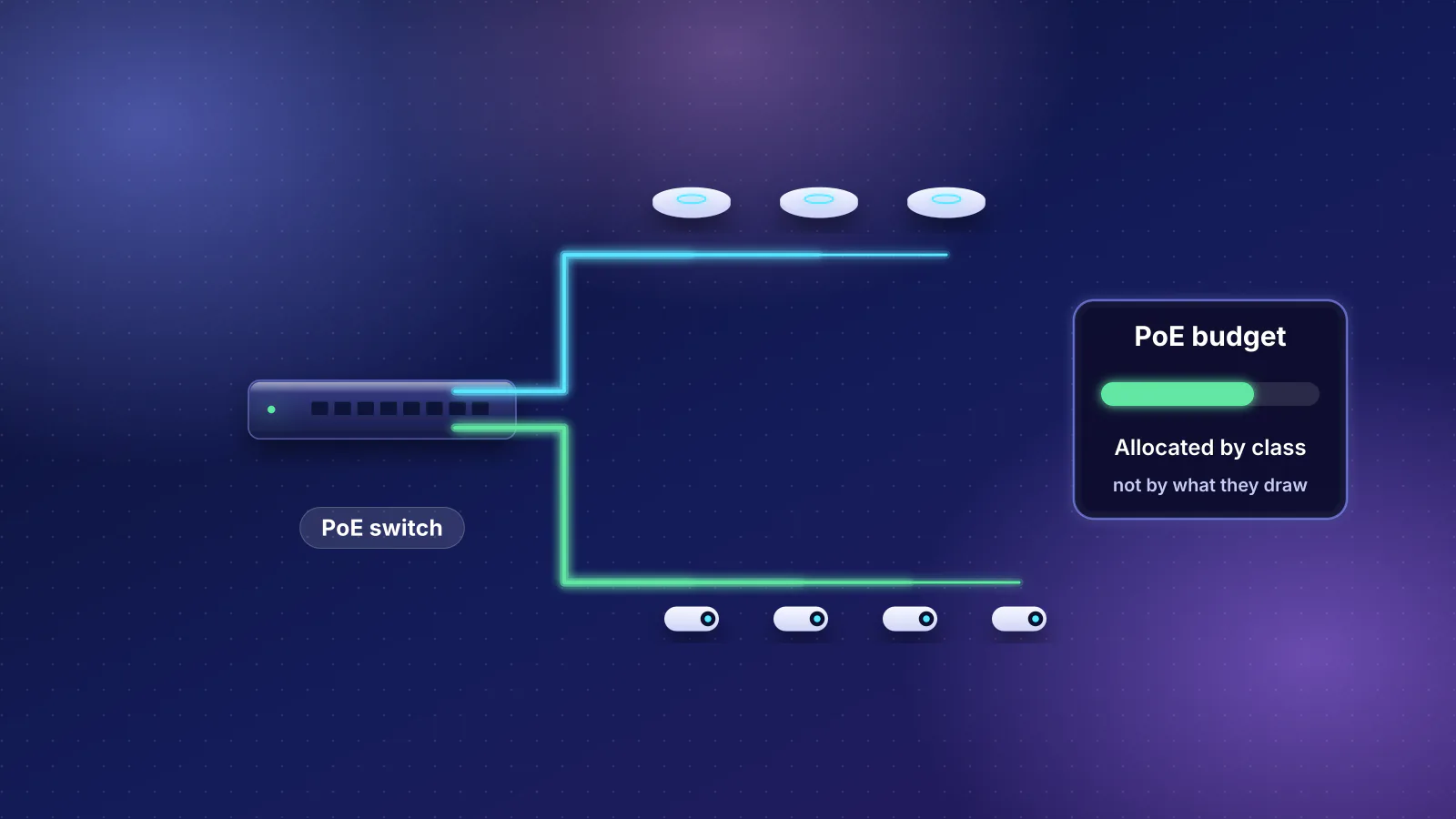
- Both cabled to a PoE+ switch at the network spot behind a router or gateway. A U7 Pro draws up to 21 W over PoE+, per Ubiquiti; PoE sizing covers the switch and what the whole design costs.
- Optional third: an outdoor access point on the back wall under the patio cover, on the same switch.
Two units can work indoors here because neither one relays the other's traffic, and each sits in the middle of its floor instead of on furniture. Ubiquiti lists 1,500 sq ft of coverage for the U7 Pro and TP-Link 1,500 for the EAP723 (TP-Link's figure is from "laboratory testing"), and two of them add up to exactly this house's floor area: no margin. The masonry rule asks for three, so treat two as a starting point that your phone has to confirm, with the outdoor AP as the planned third.
The worksheet for both layouts
| Zone | Layout A: unit | A: what lies between | Layout B: unit | B: what lies between |
|---|---|---|---|---|
| Office (front, by the garage) | Main unit | 1 interior wall | Downstairs AP | 1 to 2 interior walls |
| Living room | Main unit | Nothing | Downstairs AP | Nothing or 1 interior wall |
| Kitchen and family room | Third unit (indoor version); the main unit if the third goes outdoors | Nothing; from the main unit, 1 to 2 interior walls | Downstairs AP | Open plan or 1 interior wall |
| Guest bedroom (back corner) | Third unit (indoor version); the main unit if the third goes outdoors | 1 to 2 interior walls; from the main unit, 2 to 3: check this one | Downstairs AP | 2 interior walls: check this one |
| Loft | Upstairs satellite | Nothing | Upstairs AP | Nothing |
| Primary bedroom | Upstairs satellite | 1 to 2 interior walls | Upstairs AP | 1 to 2 interior walls |
| Back bedrooms | Upstairs satellite | 1 interior wall each | Upstairs AP | 1 interior wall each |
| Patio and pool | Outdoor unit, or the indoor third unit | Outdoor: nothing. Indoor: low-E slider or the block wall | Outdoor AP, if added | Without it: interior wall plus slider or block wall |
| Link: main unit to upstairs satellite | Wireless or cable | 1 wood floor via the stairwell | Cables | No wireless link |
| Link: main unit to third unit | Wireless or cable (outdoor version: cable) | Indoor: 1 to 2 interior walls. Outdoor: the back wall or the slider, so run the cable | Cables | No wireless link |
What the table shows: no indoor zone in either layout crosses the block or the lath. Every risk sits at the edges: the guest bedroom in Layout B (and in Layout A if the third unit goes outdoors), the floor link in Layout A, and the patio in both. Those three rows are where to measure first.
Check the result with your phone
Ubiquiti's advice for any design is to "Measure signal strength and coverage before (with mock positioning), during (as you install), and after". With a mesh kit, set units on temporary stands at the planned spots before cutting any cable; with ceiling access points, hold or tape one at the planned spot, powered from a long cable, before cutting the ceiling.
- Walk the zone list. Stand where people actually sit and read the signal strength in each zone. How to read it on a phone or laptop is in measure the signal room by room; if you have a UniFi gateway, Ubiquiti points to its WiFiman app.
- Compare with a target. Ubiquiti says "-70 dBm or better is required for stable connections" and recommends −65 dBm or better. Those two numbers match the phone's own rules: Apple's deployment guides say an iPhone keeps its current access point until the signal falls to about −70 dBm, and prefers 5 or 6 GHz over 2.4 GHz only while the signal is stronger than −65 dBm (the exact wording is in why an iPhone won't connect to 6 GHz). So a zone that reads −65 dBm or better on the phone passes; one weaker than −70 dBm fails. For a wireless link between units, Ubiquiti aims for −60 dBm and TP-Link for 2 bars in the Deco app.
- Fix a failing zone by its worksheet row. If it crosses an exterior wall, move the unit inward or add one on the zone's side. If it crosses a floor with ducts, shift the unit toward the stairs or wire the link. If it's outside, add an outdoor unit.
- Write the readings into the worksheet. They are your baseline when something changes later.
Frequently asked questions
Does stucco block Wi-Fi?
It depends on what is behind it. Stucco on concrete block is mostly a block wall, and NIST measured about 15 dB through an 8-inch hollow block wall at 5 to 5.5 GHz in the lab. Stucco on wood framing goes over metal or wire lath, which the building code requires there; eero calls walls with lath or chicken wire particularly hard for Wi-Fi, but we found no published measurement of such a wall at Wi-Fi frequencies. Either way, plan units inside the shell and measure.
Should an access point go on the ceiling or the wall?
Put a ceiling access point on the ceiling of the floor it serves. Makers such as Ubiquiti characterize them for overhead mounting and sell arm mounts so a ceiling-style AP on a wall gives similar coverage to a ceiling mount. If the wall is the only option, use a wall model such as the U7 Pro Wall or a wall-plate AP.
Will a more powerful router reach my pool?
Usually not reliably. The signal has to cross a block or stucco wall or coated glass, and in measurements the ITU has collected, coated glass ranged from no obvious penalty in one house-like building to about 20 dB more loss than plain glass in another building. An outdoor unit on a cable, from the same family as your indoor units, is the dependable fix.
Is 6 GHz worse than 5 GHz through block walls?
Only slightly in loss: in NIST's lab, an 8-inch block wall cost about 15 dB at 5 to 5.5 GHz and 16 dB at 6 to 6.5 GHz. The bigger difference in homes is that most 6 GHz access points run under the FCC's low-power indoor limits, which allow less power than some 5 GHz channels, so 6 GHz is usually strongest in the same room or the next one.
Can I put the router or an access point in the attic?
Check the operating temperature first. Ubiquiti rates the U7 Pro for ambient temperatures up to 104 °F, and eero warns that external heat sources and direct sunlight affect its units. Mount the access point in the room below and keep only the cable in the attic.
Sources
Read on November 7, 2026.
- NIST: Electromagnetic signal attenuation in construction materials, NISTIR 6055 (W. C. Stone, 1997, PDF) (laboratory losses at 0.5–2 and 3–8 GHz; block, concrete, glass, drywall and steel grid figures read from its fitted curves; loss versus density)
- Durgin, Rappaport and Xu: Measurements and models for radio path loss and penetration loss in and around homes and trees at 5.85 GHz, IEEE Transactions on Communications, November 1998 (PDF) (interior and brick wall values, foil-backed insulation, window screens, sliding doors)
- ITU-R Report P.2346-6 (06/2026): Compilation of measurement data relating to building entry loss (§6 insulation and metallized glazing; §13 US buildings at 5 GHz; §20 coated and plain glazing in Orange's Belfort building, 3.6–3.7 GHz, labelled "3 GHz"; §31.3.4 caveat on low-E glazing)
- ITU-R P.2109-2 (08/2023): Prediction of building entry loss (traditional and thermally efficient building classes, Table 1 coefficients)
- ITU-R P.2040-4 (09/2025): Effects of building materials and structures on radiowave propagation above about 100 MHz (Table 3 material properties and the attenuation-rate equation)
- ITU-R P.1238-13 (09/2025): Propagation data and prediction methods for the planning of indoor radiocommunication systems (Table 5 floor loss factors and the measured floor cases)
- Cisco: Wi-Fi 6E white paper (6 GHz band edges; free-space loss "less than 3 dB" from the bottom of U-NII-1 to the top of U-NII-8)
- ICC: 2021 International Residential Code, Chapter 7, Section R703.7.1 Lath
- eero: Where should I place my eeros?, eero PoE 7 and eero Outdoor 7
- TP-Link: Deco placement guide (updated April 17, 2026)
- NETGEAR (Australia): How many mesh Wi-Fi satellites do you need?
- Ubiquiti: AP antenna radiation patterns (overhead orientation; measure before, during and after)
- Ubiquiti: WiFi access point ceiling mounts (arm mounts for wall mounting)
- Ubiquiti: Optimizing WiFi connectivity and reducing latency (−70 and −65 dBm targets, WiFiman) and Considerations for optimal wireless mesh networks (−60 dBm between meshed APs)
- Apple Platform Deployment: Wi-Fi roaming support in Apple devices (−70 dBm roam trigger for iPhone and iPad) and How Apple devices join Wi-Fi networks (5 or 6 GHz preferred above −65 dBm on iOS and iPadOS)
- Ubiquiti tech specs: U7 Pro (mounting, coverage, operating temperature) and U7 Pro Wall
- TP-Link Omada: EAP723 ceiling-mount access point (coverage figure and its footnote)
- RouterHaus catalog (outdoor unit power, U7 Pro power draw, checked October 20, 2026) and methodology (coverage rule)